


Solutions
Horse Construction offers full range of structural strengthening materials with technical supports, documentation supports, products supports, project supports.
56 Structural Reinforcement Techniques For Bridges
56 technical methods for strengthening bridges, with pictures and texts, super practical!
1 Reinforced concrete monolithic cast-in-place simply supported slab bridge
problems

(1) There are usually multiple vertical cracks from bottom to top near the mid-span. The width of static cracks may exceed the specification limit value, sometimes accompanied by deflection in the mid-span, indicating that the bending resistance is insufficient.

(2) Longitudinal cracks at the bottom of the slab near the mid-span may generally be multiple. The width of some static cracks will also exceed the requirements of the specification. This is probably because the design drawing adopts the standard drawing reinforcement of prefabricated assembly, but the cast-in-place slab is used during construction. The way of stress causes a serious shortage of transverse reinforcement at the bottom of the board. Under the action of the transverse bending moment, longitudinal cracks are generated at the bottom of the plate.
2 Concrete precast assembly simply supported slab bridge
problems
(1) The prefabricated simply supported slab may have longitudinal cracks at the hinge joints of the bridge deck. This is mainly due to the poor construction quality of the hinge joints, resulting in poor overall connection of the plates;
(2) There may also be the phenomenon of support vacancy. Since there are 2 supports at both ends of each plate, there are more supports for each bridge. If there is an error in the elevation of the cushion stone of the support during construction, or the board is warped during the prefabrication installation, or the pier has uneven settlement, some of the supports will be vacated;
(3) There are vertical cracks from bottom to top near the bottom of the reinforced concrete slab near the mid-span, and the width of the joint may exceed the specified requirements, or there may be downward deflection in the mid-span and insufficient bending resistance.
(4) Longitudinal cracks appear at the bottom of the slab. Most of the prestressed concrete fabricated simply supported slab bridges are constructed by pretensioning. Chloride additives or concrete carbonization can cause steel bars to rust, which may cause longitudinal cracks along the bottom of the steel bar.
(5) Normal hollow slabs will not have shear diagonal cracks near the supporting end. However, in recent years, some bridges have adopted a single large hollow slab with a width of 1.5 meters or more, which is actually equivalent to a small box girder. When the plate thickness is not large, diagonal cracks may be found on the web of the side plate.

Structural Reinforcement Techniques Methods For Bridges
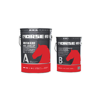
(1) For the vertical and horizontal cracks generated at the bottom of the board, when the width of the crack exceeds the specification limit, it can be reinforced by sticking steel plate method or sticking fiber composite material method. But it is not effective in solving cross-span deflection;
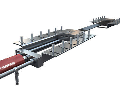
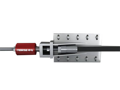
(2) Prestressed reinforcement method. A number of parallel pre-stressed thin steel wires are anchored at the bottom of the slab, and special concrete is covered after tensioning. Or set the steering bracket to stretch the bent-line cloth steel bundles, and the prestressed steel cables are anchored under the pavement layer through the inclined holes in the two end plates.


(3) Change the structural system law. If simply supported slabs are changed to continuous slabs, small-span slab bridges can be provided with piers or diagonal braces in or near the middle of the span, adopting “increasing supports in the middle of the span to change from simple support to continuous”. However, it should be noted that in the negative bending moment area of the middle fulcrum, sufficient tensile steel bars should be added in conjunction with the reconstruction of the bridge deck. The above two methods have a better effect on solving mid-span deflection;
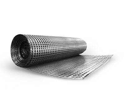
(4) Anchor shotcrete reinforcement method. After anchoring the steel mesh at the bottom of the slab, it is covered with sprayed concrete. The essence is to increase the reinforcement of the bottom of the slab, similar to the diagram of "anchoring multiple prestressed steel wires at the bottom of the slab", except that ordinary steel mesh is added to the bottom of the slab;
(5) Longitudinal cracks at the hinge joints of the bridge deck can only be solved by the reconstruction of the bridge deck, such as increasing the layout of the bridge deck transverse steel bars, thickening the paving layer, etc.
(6) The void phenomenon of the slab bridge support can be solved by replacing, adding steel backing plates, wedge tightening and other methods.
3 Reinforced concrete and prestressed concrete continuous slab bridge
Reinforced concrete and prestressed concrete continuous slab bridges generally adopt solid slab cross-section or hollow slab cross-section, and most of them adopt cast-in-place construction. If the span is less than 20 meters, the prestressed concrete continuous slab has a larger span. Generally, the post-tensioning method is adopted. There are equal heights and variable heights. There are more applications of overpasses and pedestrian bridges in urban bridges. There are more applications of reinforced concrete continuous slabs.
(1) Multiple vertical cracks from bottom to top near the bottom of the slab in the middle of each span of the reinforced concrete continuous slab bridge, which may penetrate in the transverse direction, are bending cracks, indicating that the bending resistance is insufficient;
(2) The bridge deck at the top of each pier of the reinforced concrete continuous slab bridge is cracked, and the water seepage under the bridge generally penetrates horizontally. There can be one to more cracks, which can be caused by live load or uneven settlement of the pier. The figure shows that the negative bending moment is large and the fulcrum section has insufficient bending resistance.

(3) Longitudinal cracks appear at the bottom of the slab near the middle of each span, similar to the "longitudinal cracks at the bottom of the slab at the mid-span of a monolithic slab bridge". Either the bottom of the reinforced concrete slab is insufficiently equipped with transverse steel bars, or the concrete protective layer is too thin and prestressed. The local stress of the concrete around the steel bar is too large, or the additives in the concrete cause the steel bar to rust, causing cracks along the steel bar;
(4) The deflection at the mid-span is either insufficient prestress applied, or excessive and wide vertical cracks at the bottom of the reinforced concrete slab at the mid-span, resulting in reduced rigidity and increased deflection.

Reinforced concrete and prestressed concrete continuous slab bridge
(1) For cracks at the bottom of the board, when the width of the crack exceeds the specification requirements, it can be reinforced by pasting steel plates or pasting fiber composite materials;
(2) For cracks on the bridge deck at the top of the pier, ordinary tensile steel or pre-stressed steel can be added to the concrete pavement in the negative moment area to improve the bending resistance of the fulcrum section;
(3) Pre-stressed reinforcement method, set the steering bracket at the bottom of the board, and stretch it according to the folded line-shaped bundle. This method is beneficial to various diseases caused by force.

(4) Change the structural system law. If an inclined support is added at the mid-span or near the mid-span, it can solve the problem of excessive downward deflection or insufficient prestress in the mid-span.

4 Reinforced concrete and prestressed concrete continuous slab bridge
Reinforced concrete and prestressed concrete simply supported beams are the beam bridges with the largest number of bridges in all operations, and their cross-sections often include T-shaped, I-shaped, box-shaped and various combinations. The span of reinforced concrete simply supported beams is generally 10 to 20 meters, and the span of prestressed concrete simply supported beams is generally 16 to 50 meters, with a small number of larger ones. Most of the construction methods adopt prefabricated assembly, and a few adopt cast-in-place construction. Because of the rib-shaped cross section, the dead weight is lighter and the bending capacity and span are larger than that of a slab bridge, and there are more types of diseases.
1) Reinforced concrete simply supported beam bridge
(1) The number of vertical bending cracks at the bottom of the beam near the mid-span increases with the increase of the span. The width of the cracks under the dead load may exceed the specification limit value, and some are accompanied by excessive down-deflection in the mid-span;
(2) The diagonal cracks on the web near the two supporting ends are shear diseases caused by excessive main tensile stress or insufficient web shear resistance, as shown in the figure:

(3) The vertical cracks on the beam web are mostly located in the middle of the thin web. The middle is wide and the ends are thin, and do not extend upward or downward. Most of them are shrinkage cracks caused by poor concrete curing, temperature, or too few horizontal ribs on the web, which mainly affect the durability of the structure;
(4) Longitudinal cracks along the joints of the flange plates on the bridge deck often occur in prefabricated T-beam bridges whose flanges are hinged or transversely damaged. This kind of disease will cause a vicious circle and aggravate the degree of other diseases of the single beam;
(5) Cracks caused by other construction reasons, these cracks can be found before the completion of the project.
2) Prestressed concrete simply supported beam bridge
If it is a simply-supported beam designed according to part of the prestressed concrete type B member, it is possible that there may be some diseases of the reinforced concrete simply-supported beam, but the degree is different, and will not be repeated. But it also has some common diseases with fully prestressed concrete simply supported beams. For full prestressed and partially prestressed concrete Class A members, cracks are not allowed under normal use conditions. If they occur, the cause should be found for treatment or reinforcement regardless of the width of the joint.
Prestressed concrete simply supported beams are different from other common diseases of reinforced concrete simply supported beams:
(1) The length of the longitudinal cracks under the anchors of the tension anchors generally does not exceed the beam height, which is mainly caused by the splitting tension generated by the local stress concentration under the anchors;
(2) Longitudinal cracks along the prestressed steel strands are mainly caused by the prestressed steel strand protective layer being too thin, the local stress at the steel strands being excessively large, splitting or the prestressing tendons rusting after the concrete protective layer is carbonized;
(3) The mid-span downward deflection is too large to exceed the allowable value of the specification, and the mid-span section may not crack. Mainly due to insufficient prestress or excessive prestress loss.
bridge strengthening
(1) The bending cracks at the bottom of the beam and the longitudinal cracks along the prestressed tendons can be reinforced by pasting steel plates and pasting fiber composite materials. It can also be reinforced by increasing the cross-section method, increasing the thickness of the paving layer, and increasing the area of the cross-section compression zone is beneficial to improving the bending strength and rigidity. However, the increase in height is limited, and the self-weight is also increased. If the height of the bottom section of the beam is increased, it is actually an increase in reinforcement;
(2) For oblique cracks on the web, it can be opposite to the crack and approximately 45° to the horizontal. That is, the steel plate or fiber composite material is pasted roughly perpendicular to the direction of the oblique crack. When the beam height is short and the steel plate or fiber anchor length is insufficient, it can be pasted in the form of U-shaped hoop and pressure strip.

3) For the shrinkage cracks on the web and the cracks in the anchoring area, epoxy glue is used to seal or fill the joints depending on the width of the joints;
(4) For longitudinal cracks on the bridge deck, the thickness and transverse reinforcement can be increased in combination with the modification of the pavement layer, or the transverse partition can be increased or enlarged;
(5) The above-mentioned various diseases caused by force can be reinforced by external prestressing method. There are many specific methods. The design and construction of this method are complicated, but the effect is better.

(6) For a single-piece beam with more diseases and heavier, when conditions permit, the transverse connection can be cut to replace a new beam with increased rigidity, while reducing the load distribution of other beams. In most cases, the side beams are seriously diseased, as shown in the figure:

You can find anything here you are in need of, have a trust trying on these products, you will find the big difference after that.

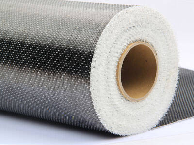
High strength, unidirectional carbon fiber wrap pre-saturated to form a carbon fiber reinforced polymer (CFRP) wrap used to strengthen structural concrete elements.

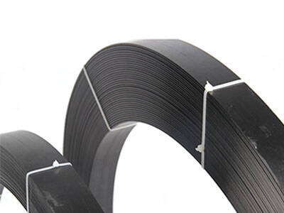
High strength carbon fiber reinforced polymer (CFRP) strip / laminate / plate for structural strengthening and concrete repair

High strength, unidirectional carbon fiber sheet pre-saturated to form a carbon fiber reinforced polymer (CFRP) sheet used to strengthen structural concrete elements.
